Uncategorized

What is Insulation Extrusion Production Line?

What is Insulation Extrusion Production Line

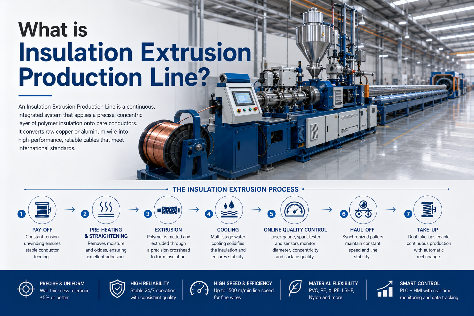
An Insulation Extrusion Production Line is a continuous, fully integrated industrial manufacturing system specifically engineered to apply a precise, concentric layer of polymer insulation onto bare metallic conductors (copper or aluminum). This process converts raw conductors into finished insulated wires and cables that meet rigorous international standards for electrical performance, mechanical strength, flame retardancy, and long-term reliability.

It is widely regarded as the core equipment in any modern cable factory. From high-volume building wires (THHN/THWN, BV, BVV) and low-voltage power cables to control cables, electronic wires, and specialty constructions, virtually every insulated electrical product passes through an insulation extrusion line.

Professional lines today combine high-speed capability, closed-loop quality control, energy-efficient design, and material flexibility — delivering consistent wall thickness tolerance of ±5% or better, excellent concentricity, and stable 24/7 production.

How an Insulation Extrusion Production Line Works – Step-by-Step Process

The insulation extrusion process is a continuous, synchronized sequence of operations:

  1. Pay-off Stage Bare conductor is unwound from single or dual-cone pay-offs (typically Ø400–1250 mm reels) under precise tension control. Automatic dancer or sensor systems maintain constant tension to prevent stretching, breakage, or eccentricity.
  2. Pre-heating and Straightening The conductor passes through an induction or infrared preheater (usually heated to 80–150°C depending on material). This removes surface moisture and oxides while improving adhesion between the conductor and molten polymer. A straightener eliminates residual torsion.
  3. Extrusion Stage – The Heart of the Process Polymer granules enter the extruder hopper and are conveyed by a rotating screw through three functional zones inside a heated barrel:
    • Feed Zone: Conveys solid pellets and begins softening.
    • Compression (Transition) Zone: Melts the polymer through external heat and shear friction while purging trapped air.
    • Metering Zone: Homogenizes the melt and pumps it at stable pressure toward the crosshead.
    Typical screw L/D ratios range from 24:1 to 30:1 for PVC, PE, and XLPE. Melt temperatures vary by material (PVC approx. 160–190°C, PE 180–220°C, XLPE 200–280°C depending on crosslinking method). The molten polymer is forced through a precision crosshead die surrounding the moving conductor, forming a continuous concentric insulation layer under controlled pressure (commonly 10–30 MPa).
  4. Cooling and Solidification The coated wire immediately enters multi-stage water cooling troughs (often 10–25 meters long). Controlled water temperature prevents internal stress, voids, or surface defects while allowing the insulation to contract uniformly around the conductor.
  5. Online Quality Control Laser diameter gauges provide real-time feedback to the extruder and haul-off for closed-loop diameter control. Spark testers detect pinholes or thin spots. Optional eccentricity monitors, lump detectors, and surface scanners further ensure quality.
  6. Haul-off (Capstan) and Take-up Synchronized caterpillar or belt pullers maintain constant line speed. Dual automatic take-ups allow continuous operation during reel changes. Accumulators act as buffers to prevent stoppages.

Modern lines support single-layer insulation, co-extrusion (skin/stripe), dual-layer, and tandem configurations (e.g., PVC insulation + Nylon jacket for THHN/THWN in one pass).

Core Components Explained in Detail

  • Pay-off System: Dual-cone or flyer type with electromagnetic or pneumatic braking for stable tension.
  • Preheater & Straightener: Critical for adhesion and concentricity.
  • Extruder: Single-screw (most common) or multi-extruder setups. Bimetallic barrels for abrasive compounds such as LSHF.
  • Crosshead & Tooling: Pressure tooling for strong adhesion or tubing tooling for higher flexibility. Tungsten-carbide dies ensure precision (±0.02 mm).
  • Cooling Troughs: Multi-zone with temperature control and air-wipe systems.
  • Diameter Gauge & Spark Tester: Closed-loop control for real-time adjustment.
  • Capstan / Haul-off: Servo-driven for speed stability up to 1500 m/min on fine wires.
  • Accumulator & Dual Take-up: Enable non-stop production.
  • PLC + HMI Control System: Recipe storage, automatic diameter control, alarm diagnostics, and Industry 4.0 connectivity.

Optional systems include gravimetric dosing, automatic dryers, color masterbatch metering, online printers, and aluminum-strip taping..

Materials, Temperature Profiles, and Tooling Considerations

Common insulation materials include:

  • PVC (cost-effective, flexible, widely used for building wires)
  • PE / HDPE / LDPE
  • XLPE (silane or peroxide cross-linked for higher temperature ratings)
  • LSHF / HFFR (low-smoke halogen-free for fire-safety applications)
  • Nylon (PA) for abrasion-resistant outer jackets
  • TPU, TPE, and specialty compounds

Typical Temperature Profiles (approximate):

  • PVC: Feed 160–170°C → Compression 170–180°C → Metering 175–185°C → Head 180–190°C
  • PE: Higher zones around 190–220°C
  • XLPE: Often 200–280°C depending on crosslinking technology

Draw-down ratio (DDR) and draw-balance ratio (DRB) are carefully calculated for each material and tooling set to achieve optimal surface finish, concentricity, and material efficiency.

Technical Specification Overview (Representative Models)

Model ClassScrew DiameterConductor RangeMax. Line SpeedTypical Output (PVC)Primary Application
Compact45–70 mm0.5–16 mm²600–1500 m/min100–200 kg/hElectronic & fine building wire
Mid-range80–100 mm10–240 mm²150–350 m/min250–350 kg/hPower & control cables
Heavy-duty120–150 mm50–1000 mm²45–150 m/min400–600 kg/hLarge power & specialty cables

Actual performance depends on wall thickness, compound viscosity, and cooling capacity. Closed-loop systems routinely achieve wall-thickness tolerance of ±5% and concentricity error ≤5%.

Main Applications Across Cable Types

  • Building & Installation Wires: High-speed PVC or XLPE insulation, including tandem Nylon for THHN/THWN.
  • Power Cables: Single or multi-layer XLPE / LSHF for low- and medium-voltage applications.
  • Control & Instrumentation Cables: Precise concentric insulation for reliable signal transmission.
  • Electronic & Automotive Wires: Fine-gauge high-speed lines for UL-series, FLRY, H05V-K, etc.
  • Data & Telecommunication Cables: PE or specialized compounds requiring low dielectric constant and tight tolerances.

Key Advantages of a Professional Insulation Extrusion Production Line

  • Consistent product quality with minimal eccentricity and voids
  • High productivity (line speeds up to 1500 m/min on suitable products)
  • Significant energy savings (modern designs can reduce consumption by up to 25% versus conventional extruders)
  • Reduced scrap rates through real-time closed-loop control
  • Material flexibility and quick changeover capability
  • Full compliance with UL, IEC, GB/T, BS, and VDE standards
  • Lower total cost of ownership through reliability and reduced downtime
  • Support for Industry 4.0 features (remote monitoring, predictive maintenance, recipe management)

How to Select the Right Insulation Extrusion Production Line

Professional buyers evaluate:

  1. Exact conductor size range and product mix
  2. Primary materials (PVC-only vs multi-material including LSHF/XLPE)
  3. Required daily/weekly output and target line speeds
  4. Quality-control features (laser diameter feedback, spark testing, eccentricity monitoring)
  5. Energy efficiency and cooling system capacity
  6. Automation level and Industry 4.0 readiness
  7. Supplier engineering capability, customization support, spare-parts availability, and long-term technical partnership

A well-matched line typically delivers measurable ROI through higher throughput, lower scrap, and reduced energy costs within 12–24 months.

Common Challenges and Proven Solutions

ChallengeTypical CauseProfessional Solution
Uneven wall thickness / eccentricityIncorrect die centering or tension fluctuationPrecision die alignment + closed-loop laser control
Air bubbles / voidsMoisture in compound or overheatingProper drying + optimized temperature profile
Surface roughness or scorchingIncorrect melt temperature or die wearTemperature calibration + regular die maintenance
Color inconsistencyPoor masterbatch dispersionGravimetric dosing + pre-compounded materials

Addressing these issues at the equipment selection stage significantly improves first-pass yield and reduces field failures.

Ready to equip your factory with a reliable, customized Insulation Extrusion Production Line?

Our engineering team provides complete process analysis, customized screw & die design, full line layout drawings, capacity calculations, installation supervision, operator training, and ongoing technical support. We focus on reliable quality, tailored solutions, and long-term partnership.

Inquiry Now – Contact us today for a detailed technical proposal and quotation matched to your specific conductor range, materials, and production targets.

Leave a Reply

Your email address will not be published. Required fields are marked *